
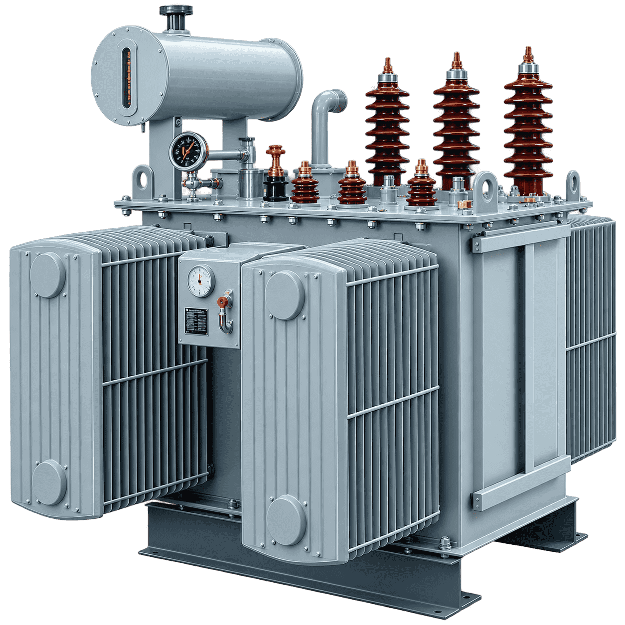
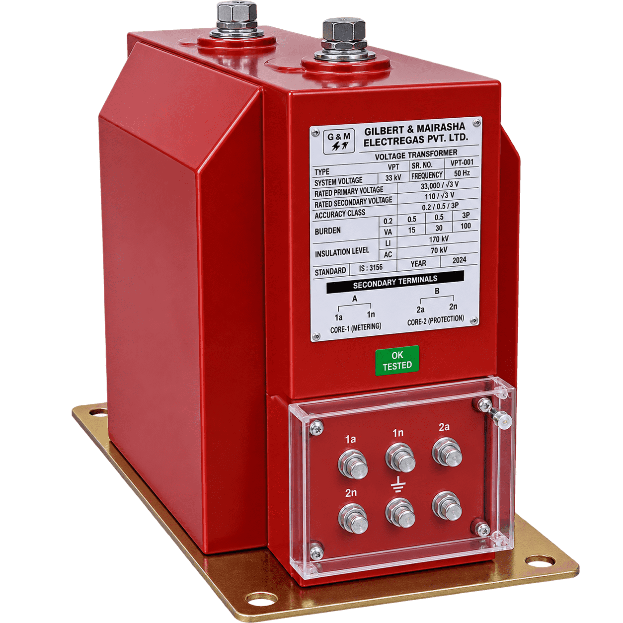
Oil Immersed Distribution Transformer
STANDARD FITTINGS
-
H. V. Bushing
-
L. V. Bushing
-
Off-Circuit Tap Changer
-
Conservator oil filling hole with cap & drain plug
-
Undercarriage with four bi-directional rollers
-
Earthing terminals
-
Drain cum bottom filter valve with sampling plug.
-
Top filter valve with sampling plug
-
Plain Oil Level gauge
-
Rating diagram plate
-
Air release device
-
Thermometer Pocket
-
Lifting lugs
-
Pressed Steel Radiators (Fins or corrugated type)
-
Double Diaphragm Explosion Vent
-
Silica gel breather
-
Additional Neutral bushing
-
First filling of oil
TECHNICAL SPECIFICATIONS
| Parameter | Specification |
|---|---|
| Duty, Type | Outdoor / Indoor, Pole or Ground Mounted |
| Voltage Class | 3.3, 6.6, 11, 22, 33 kV or any specific |
| No of Phases | 1 or 3 Phase |
| Frequency | 50/60 Hz |
| Vector Group | Dyn1 or Dyn5 or Dyn11 or any specific |
| Insulating Fluid | PCB FREE Mineral Oil, both inhibited & uninhibited, as per IS/IEC, ASTM D3487 and customer requirement |
| Class of Insulation | Class A |
| Tap Changer | Off Circuit or On Load |
| Tapping Range | ±2.5% X 2 for OCTC or + 1.25% X 4 & - 1.25% X 8 for OLTC or as per customer requirement |
| Winding Material | Aluminium or Copper with multi-paper covering |
| Applicable Standards | IS 2026, IEC 60076, ANSI, IEEE |
| Painting | Enamel, Epoxy, Polyurethane or customer-specific |
OPTIONAL FITTINGS
-
Detachable Radiators with isolating valves.
-
Jacking Pads
-
Dial-type Oil Temperature Indicator with A/T contacts
-
Dial-type winding temperature indicator with A/T contacts
-
Magnetic Oil Gauge with A/T contacts
-
Buchholz relay with A/T contacts
-
Marshalling box with control wiring
-
Equaliser pipe between conservator & explosion vent
-
On-load tap changer
-
RTCC Panel with automatic voltage Regulator (AVR)
-
Pressure Release valve
-
DGPT Relay
ASSURED FEATURES
-
Highest dielectric insulation property to withstand Lightening Impulse.
-
Mechanical design to withstand short-circuit forces arising during faults.
-
Optimum oven heating under vacuum as to achieve desired compression height and maximum insulation resistance (IR) to windings.
-
Adequate ducts between layers, coils, and discs for maximum oil flow and reduced hot spot temperature.
-
Step-lap designed CRGO laminations for lower losses and excitation current.
-
Pre-compressed insulation material for minimal moisture absorption.